"XPLSISNJASP-hardware"
![]()
"XPLSISNJASP-hardware"
![]()
"Xmms Parport Light Show IS Not
Just A Software Project !!! "
Hello , this is a little strange name for plugin , but here it is :-)))
For this plugin to work you
must have this plugin installed on your computer and xmms 0.9.5.1
working.
Here you gonna find shematics and little information
on how to build you Light-show hardware part. First you must have some
basic
knowledge about electronic design and building
the electronic circuits...
It's low cost circuit and parts are available
in every electronic parts store ...
First:
You
need these components...
Q1-Q8
= LTV02VC or similar optocoupler
Q9
= LM 7805 5V+ stabilisator or similar
Q10
= Greatz ( you may build it with four 1N4001, 1N4148 diodes or something
like that ...)
T1-T8
= TIC106M Thyristor or similar...
R1-R8
= 1 Kohm resistors 0.25 Watt
R9-R16
= 220 Kohm resistors 0.25 Watt
B1-B8
= Light Bulbs about 75 Watts /220V AC or something like that
...
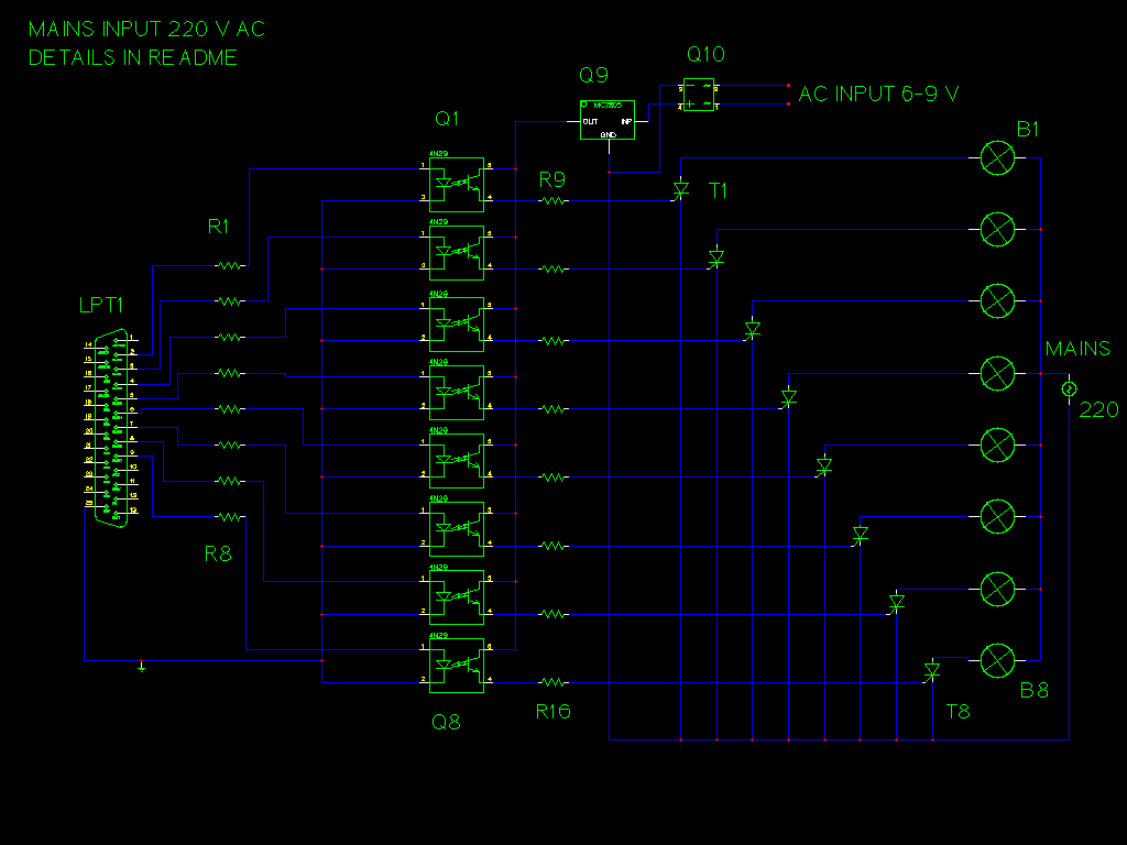
Here is the picture of Shematic:
It is created in gEDA
gschem and taken out in PNG ....
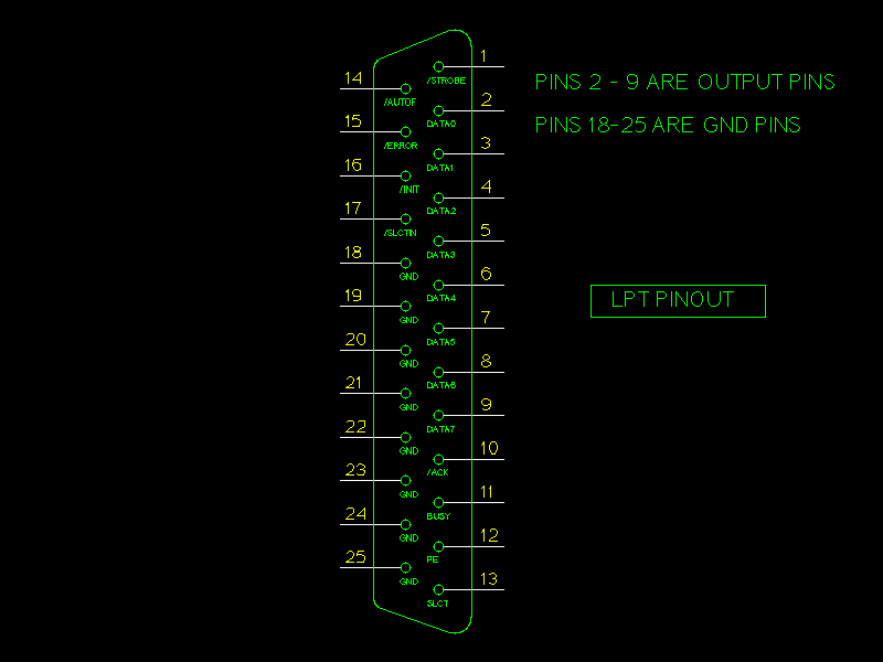
Here is a image of Parallel Port output connector
which is on your computer.
Please be carefully when connecting something
to this connector , bicouse you may loose it forever (burn it !!!).
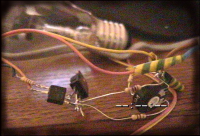
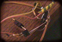
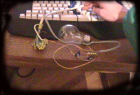
Some images taken from very first working version one channel only (
it actually works! )
Just for info : Images are taken with SONY CCD-TR402E
PAl handycam trough Miro PCTV on XawTV in LINUX !!!
How it works ?
Simply !
Xplsisnjasp puts data in rhythm
of music on your output pins on LPT port . Then that signals are come trough
1 Kohm resistors on
anode of LED-diode in optocoupler. In that moment
a 5V flows trough E-C of transistor in optocoupler and it goes on 220Kohm
resistor and then on thyristor G. It opens it and then light bulb flashes...
When is no data on output pin, E-C of transistor
in optocoupler don't let current trough and there is no signal on thyristor
which is in that way closed and no current goes trough bulb .
That's it ...
Now you just make a printed
board and put all these components toghether.
That circuit is not complicated at all , and
i created it with no printed board at all, just bunch of wires.
But please be careful with pinout for thyristors
and mains supply. Nothing is going to happend to your computer if you put
these optocouplers right. Oh, that reminds me; Thanx to
k0st for testing version without optocouplers !!!!!!! :-) buum...
This project is free to use and build but i give
no garanties for your life nad your computer to work after this one !
Please notice that this is just a simple and
poor fast designed circuit build with amater components...
There is no way that mains supply get in your
PC if you build this as i wrote !
If you like to recieve and printed board layout please mail me and we think of something....
This Project is developed in HULK podruznica Nasice by: Sinisa Dukaric & Vlatko Kosturjak
DOWNLOAD AREA:
Please get software packages
at this site:
http://www.na.linux.hr/projects/xplsisnjasp/

That's it , now put these thing together and have a lot of fun :-)))
Sinisa Dukaric : starcracker
Vlatko Kosturjak: kost
Please visit our main site at : www.linux.hr
![]()
![]()